Help me with VLAN setup

A homelab is such a great learning opportunity! I’m even more convinced now that Pubmox will be of great service to our community.

Here’s the story: Yesterday, I made a few changes to my physical homelab setup in preparation for the Pubmox project. Proxmox server, Synology NAS and the new 2.5G switch are now sitting together nicely on my office shelf, all connected to my UPS.

But when I tried to use the JetKVM, I got immediate disconnection errors. This only happened when it was connected to the Pubmox VLAN 7, but not with the default Home VLAN 1. It took me a bit of thinking to realize what was happening.

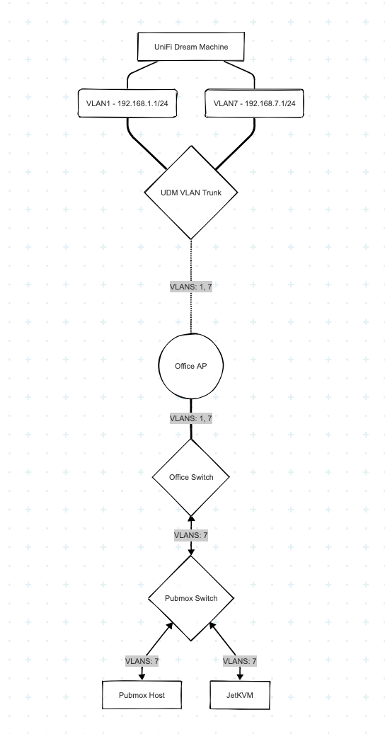
This is how my network is set up:

UDM == Office AP -- Office Switch -- Pubmox Switch

The Unifi Dream Machine, my internet router, sits downstairs where the cable internet comes in. Since I can’t run cables, I’m using a Wi-Fi bridge (==) to connect my office upstairs. In the office, I’m running the Pubmox Switch on the shelf via POE off the Office Switch under my desk.

Here’s what, I think, is happening: As long as I only use VLAN 1, my Office switch sends packets directly to the Pubmox switch.

But any packet from VLAN 1 to VLAN 7 first goes downstairs via Wi-Fi, just to be routed back upstairs again. In consequence, any TCP roundtrip would pass the Wi-Fi bridge four (!) times.

Am I right in this conclusion?

If so, the question is how to solve this.

Is there a way to set up layer 2 so the Office Switch talks to the Pubmox switch for VLAN 7 packets? Would it help to declare the port on the Office Switch connecting to the Pubmox Switch as “VLAN 7 only”? I’d have to run cables to the Office Switch for personal devices on the shelf, but cables are cheaper than the other option.

The other option being to replace the Office Switch with a layer 3 switch. Heh, I learned about layer 3 switches only last night! That’s what I meant by a homelab being great for learning. A layer 3 switch would be able to make real routing decisions on its own, without involving the main router downstairs.

Any hints from someone who’s more experienced in networking than me would be greatly appreciated.

Oh man, I think I found an exciting solution! But I’d love to see what you can come up with first.

The diagram you’ve provided gives us kind of a rough Layer 1 diagram, but doesn’t really show us Layers 2 or 3 to really grok what’s going on here. Recreating what you’ve got in a more visual diagram, this is what I think you’re illustrating for your Layer 1 setup.

Based on what you’ve described, I imagine the original hybrid L2/L3 to look like this:

Given the model you’ve described, you are correct - your traffic is going down to your UDM to route to the Pubmox network. To answer your question though, “Is there some way to set up Layer 2 to not have traffic go down to the UDM”, the short answer is no. To get traffic from the network on VLAN 1 to the network on VLAN 7, you need to route it there. Good thing we have these cool things called routers!

In your network topology, I don’t think it makes sense for you to have VLAN 7’s router live on the UDM. It makes more sense IMO for that router to live on the other side of the WiFi bridge. If your Office Switch has “smart switch” (basic L3) capabilities, you could have it serve as the router for the Pubmox network. This switch would also need an IP on VLAN 1’s network, and devices on VLAN 1 would need routes that inform them they can reach VLAN 7’s network via the other router. If a switch can’t do this, VLAN 1 could also be extended to the Pubmox switch for it to run a router VM, and it could also act as the router. Same caveats apply.

There’s other alternatives as well - segregating your office to a separate L3 network with a router on the other side of the bridge that can route to VLAN 1 and VLAN 7’s networks. This would help avoid the static route population work necessary, assuming there’s enough devices that this would be an issue.

You got it right, this is how the network is configured. Well done, also on the diagrams!

Unfortunately, both switches are layer 2 only. Had I researched the VLAN concept better ahead of ordering the new switch, I could have picked one with layer 3 capabilities.

You’re spot on that the VLAN router should be located in my office, not downstairs across the Wi-Fi bridge. I did not think of this at first because adding another network component sounded so daunting (i.e. expensive). This was probably influenced by me hearing about routers mostly in the data centre context. But when I put in a bit more thought, I realized I won’t have to spend more money.

When I said I had an exciting idea, what I meant was that I can easily build a router in software on my homelab Proxmox server. This will allow me to learn about OPNsense!

The router will have one virtual NIC for the LAN trunk, and one for each additional VLAN (7 for now). For the VLANs, it will run DHCP, routing, and firewall. This way, I can get as many broadcast domains in my office as necessary.

Some background knowledge for anyone even less familiar with networking than I am.

The various concepts related to networks are usually organized into layers (of abstraction). The most commonly used model here is the OSI model.

Layer 1: Physical layer

Only devices that are connected directly via hardware such as copper wires or optical cables can talk to each other. Here, Ethernet has emerged as the standard, while other approaches such as Token Ring became extinct.

In early Ethernet standards such as IEEE 10Base-2, multiple devices tapped into the same cable. The “one cable per device connection” approach took over once it became affordable.

Layer 2: Data link layer

At this level, we’re starting to look at the actual data that’s being transmitted. Ethernet uses MAC addresses to determine sender and receiver. Packets are distributed throughout the broadcast domain, that is, to all connected devices, in the hope that they’ll be picked up by the device that has the destination MAC address.

Layer 2 devices such as hubs and switches extend the broadcast domain to as many devices as necessary. While hubs indiscriminately spam everyone with every packet, network switches keep track of which MAC address is behind which switch port, which greatly reduces broadcast traffic. Again, switches fully replaced hubs when it became economical.

VLANs (virtual LANs) were introduced later to further segregate broadcast domains. Network packets may now also carry a VLAN tag that determines the virtual LAN they’re meant for. VLAN-aware switches can decide which ports to use (or block) based on VLAN tag.

Layer 3: Network layer

This is the realm of the Internet Protocol, where we talk about IP addresses and subnets. On this layer, we’re not limited to shouting across broadcast domains any more. Devices called routers instead use rules to clearly determine the peer to which to hand packets so they reach their destination host most efficiently. In consequence, that host can now be anywhere on the planet.

DHCP is a way to use the underlying data link layer to automatically get an IP address for a host. The host broadcasts a DHCP request, and the DHCP server responds with a free IP address from its address pool.

Layer 4: Transport layer

With layer 4 and above, we’re reaching levels of abstraction that get us gradually into the realm of software applications.

On layer 4, we have the TCP protocol that, among other things, adds a port number that gives us the ability to address a specific service on the host specified by the IP address from level 3. For example, “this TCP packet is meant for host X on its port 80 because it’s an HTTP packet”.

How this applies to my setup

The problem I have to solve is that I want to run multiple IP (layer 3) networks on the same data link layer (aka my home network).

I could try and simply assign different IP addresses from a separate subnet to the Pubmox hosts. I won’t be able to use DHCP for automatic assignment since, in this approach, I have only one broadcast domain (i.e. hardware network), and the DHCP server on my main router will automatically assign addresses for my personal address pool. Instead, I could use static addresses. The reason I did not take this approach is that running my personal devices side-by-side with community infrastructure offers no security at all. That approach also has a critical flaw that I missed; more on that below.

I opted for introducing a separate Pubmox VLAN. I can force my switches to tag all packets coming from Pubmox hosts as “VLAN 7”. By disallowing VLAN 7 packets on ports connecting critical personal machines, I can isolate my networks on layer 2. My main router can assign DHCP addresses separately by VLAN, so Pubmox hosts will get addresses from the Pubmox subnet. And with separate IP subnets, I can use the firewall on my main router to improve security on layer 3 as well.

What I missed was the fact stated earlier, that, VLAN or not, there always has to be a router to handle the transition of IP packets from one subnet to the other. Even if those subnets share the same layer 2 infrastructure, there has to be a router that has a leg in each IP network and applies rules for what to forward to where.

Up to now, this role has been fulfilled by the only router I have, the Unifi Dream Machine in our living room. It’s where I set up VLAN 7 with its own IP subnet. It serves DHCP requests for both VLANs, and applies firewall rules to traffic between the IP subnets. Another detail I missed was that it also tags packets destined for Pubmox hosts with “VLAN 7”.

This would all be grand if there wasn’t a Wi-Fi connection between my office and the UDM downstairs. Every network packet from Office Land to Pubmox Land goes across the radio, gets routed promptly back upstairs, and the related response packet has to go through the same downstairs-upstairs journey again. This causes tremendous latency and potential for transmission errors. I might not have noticed the problem immediately with web traffic, but the RTMP connection from the JetKVM’s video feed made it obvious right away.

And that’s why I’m going to build a virtual router on my personal Proxmox server. I will be sharing my learnings and experiences with you, of course!

And here I am with the learnings. And they didn’t get any less strange, too!

New VLAN setup

So yesterday, I set up OPNsense on my homelab. After pushing my network (and my running live stream with it) off the cliff by letting OPNsense occupy my UDM’s IP address, I used its fantastic console startup menu to redefine the disrupting network interface, and we were off to the races.

Even though I had given the OPNsense VM two virtual NICs, I ended up using only one. It is based in my homelab network as a trunk connection, transporting both the internet-bound traffic and the TSR-bound one. In OPNsense, I added a sub-interface tagged with the TSR VLAN. This VLAN interface has DHCP and DNS services attached.

On the TSR lab switch, I set the TSR VLAN as the native LAN for all the relevant ports.

So far, so good.

Setting up Pubmox

Now came the Proxmox setup. I connected the JetKVM, and it got a TSR IP address. On my workstation, I set a static route for the TSR VLAN via OPNsense, and pulled up the JetKVM web UI. And again, the video connection started breaking up within seconds, with lots of packet loss on my workstation. I checked with traceroute that my routing didn’t involve the WiFi, and it all looks okay to me.

The new LAN setup had not changed anything about the KVM issue. WTF.

I did a lot of testing, but could not find the fault. With the JetKVM in my homelab network, it works great. In the TSR network, effectively not at all.

I ended up installing Proxmox via the JetKVM in my homelab network. Took me only a few minutes. A KVM surely is a handy tool.

The clincher

And now comes the strangest thing. I spun up my laptop, and was able to connect to the JetKVM connected the TSR LAN without issues. And since the laptop is using WiFi, its traffic runs between the UDM downstairs and the TSR LAN upstairs back and forth. Apparently, the few ms of latency don’t really matter after all.

So it must be something with my workstation. I have no idea what it could be. Any hints will therefore be highly appreciated.

Just now getting back to this one, sorry about that. If I had to guess here, there might be an MTU (Maximum Transmission Unit) / TCP MSS (Maximum Segment Size) issue with the introduction of VLAN tagging. An as of yet unanswered post on the OPNsense forums notes a similar issue: With VLAN I need to manually set MSS. Why?

When PMTU discovery isn’t working correctly, and there’s an assumption of an MTU / TCP MSS that is larger than what the interface can handle, the end result is indeed packet loss, so it would seem to track. As to why your laptop is discovering things correctly and the workstation is not? That’s gonna need more digging.

MTU mismatch sounds plausible, I’ll look into that. Thanks for the tip!